Objectives:
- Know what is parametric drawing
- Know how to identify when a CAD drawing is parametric
- Know how to use Parametric Drawing in a design
- tasked to create our own Fusion 360 Parametric Drawing of a Handphone Holder.
--------------------------------------------------------------------------------------------------------------
What is Parametric Drawing?
Parametric modeling is a computer aided design (CAD) software design tool that saves time—it eliminates the need for a design engineer to constantly redraw a design every time one of the design’s dimensions change. A parametric model contains information like dimensions, constraints, and relationships between various entities which is why one can easily make changes to the design, and it updates and responds to those changes. A non-parametric model does not contain such relationships.
Practice - Parametric Drawing
To ensure that i was prepared and knew how to create my own Parametric Drawing on Fusion 360, as so far i have only practiced drawing a mere keychain, i referred to this video: https://youtu.be/m5gl8N2t6_E and followed the steps exactly to recreate this bracket on FUsion 360:
Creating my Personalised Handphone Holder (using Parametric):
Meanwhile here's the final product! To see how i did it, scroll down below for a detailed tutorial!
** I also explained along the way how is my design deemed Parametric along the way in red and blue notes :)
-------------------------------------------------------------------------------------------------------------
Step 1: Open Fusion 360 and click 'Create Sketch" (See red circle)
Note: To ensure it is a Parametric Design, it means that you need to set a relationship between entities e.g. dimensions, constraints etc (as mentioned above) so that it will always be easy for you to change the dimension of the product you wish to make. Likewise, as we are creating a PARAMETRIC handphone holder, we will form a relationship between the dimensions and pre-set them.
What do i mean? See Step 2 and 3!
Step 2: Click on "Modify" (See red circle 1) then click on "Change Parameters" (See red circle 2)
Step 3: Click on the "+" Sign (See red circle), from which a smaller box - "Add User Parameter" will pop up.
Then,
- Type in the 'Name' of the dimension you want to add i.e. "Length" (see yellow highlighted),
- Check that the Unit is 'mm' (See Pink Highlighted)
- Type in under 'Expression' (See Green Highlighted) the number denoting how long/short your dimension you want to set at i.e. 145mm
And Click 'OK' (See Blue Arrow)
Step 4: Then, continue Adding for whatever Dimensions you deem necessary to be Specified, the exact same way we just did for 1 i.e. Length in Step 3.
Note: To create this Specific Design, I added:
- "Device Height -> 145mm",
- "Device Width -> 69mm",
- "Device Thickness -> 8.5mm",
- "ply -> (1 /8) * 1 in" => Note: (For Ply, this refers to thickness of the material which would be used in Laser cutting this product. This numerical value can be changed depending on what material is used e.g. maybe a quarter inch plywood might be used, so instead of inputting 1/8in, we would then input 1/4in instead after measuring the thickness with a caliper before laser-cutting this product) !! This is the benefit of Parametric Drawing, lets say you dont have 1/8 inch plywood on hand when you wish to laser-cut your product, so instead of having to redraw the dimension according to the material you have on hand, you just have to change the value you inputted to suit your resources (as explained above in blue)
- "Border -> 15mm" => Border of the tray that holds the handphone
- "Angle -> 105 Degree" => I added this dimension so that if i want to change the angle at which the handphone lays down on the tray its possible.
Then, Click 'OK' (see green highlighted)
Step 5: Before we can actually start drawing, as this design has many components, we have to Click "Create" -> "New Component" -> Rename to "Leg 1" -> Click 'OK'
Step 6: Start Drawing -> Click the 'Line' icon (See red circle) and start Drawing the shape of the leg component:
1. Draw a Line to your right
2. From there, Draw a 90 degree line upwards,
3. From there, draw a short 90 degree line to your left
4. Draw a Diagonal line down
5. From there, Draw upwards at 90 degrees
6. From there, draw a short 90 line downwards connecting to the y-axis
7. From there, draw vertically downwards to the origin
This is what you should see:
** If your lines are not 90 degrees when you need them to be:
Select the 2 lines you want to be perpendicular -> Click 'Constraints' -> Click 'Perpendicular'
Like so:
Step 7: Input the dimensions
First, Select the 2 yellow highlighted lines -> Click 'Sketch Dimension icon' (see red circle), in the box that appears -> type in your predefined 'Angle' dimension and it will automatically set the angle between both lines to it.
You can also change this angle in the Parameters you've set just now [This is why it is a Parametric Drawing]
Step 8: Select the green highlighted line-> Click 'Sketch Dimension' -> Type 'DeviceWidth + Border + Ply'
(all these dimensions have been pre-defined, now we just create a formula using them for this dimension)
Step 9: Select the green highlighted line-> Click 'Sketch Dimension' -> Type 'DeviceThickness + (ply*3)'
Step 10: Select the green highlighted line-> Click 'Sketch Dimension' -> Type ' 20mm'
So far, this is what you should see:
(It should resemble somewhat like this, it may differ abit if you drew some lines longer than me for now but later on when we define all dimensions it will be exactly the same, dont worry :))
Step 11: As this is the Leg component, Lets draw some 'Legs at the Base'
Click "line icon" -> From the Bottom, Draw a shape that looks like this eventually (See red circle):
Step 12: Now we will add some dimensions
Select the green highlighted lines -> Click 'Sketch Dimensions' -> Type 'Angle"
Repeat the same for the opposite 2 sides
Step 13: Select the 2 yellow dots -> Click 'Sketch Dimension' -> Type '10mm'
Do the same for the 2 green dots
Step 14: Select the 2 pink dots -> Click 'Sketch Dimension' -> Type '20mm'
Step 15: Select the 2 pink dots -> Click 'Sketch Dimension' -> Type '10mm'
Step 16: Select the 2 Points highlighted in Pink -> Click 'Sketch Dimension' -> Type 'Device Width/2'
It should look like this so far..
Step 17: Draw 2 rectangle shapes (Tabs) on the Diagonal Surface of the Drawing so far
Step 18: Draw 1 rectangle shape (Tab) on the surface that has the dimension '18.025'
Step 19: Select the pink highlighted line -> Click Sketch Dimension -> Type 'Ply'
Repeat this step for the yellow and green highlighted lines:
Step 20: Select the green highlighted lines -> Click Sketch Dimension -> Type 'Ply*1.5'
Repeat the step by selecting the pink line and the pink dot instead
So that now, Both the green and Pink line are Equidistant:
Step 21: Select the Green Line -> Click Sketch Dimension -> Type '25mm'
Repeat for the yellow line
Step 22: Select the 2 yellow Lines -> Click Sketch Dimension -> Type 'ply*3'

Step 23: Repeat Step 22 by selecting the Yellow line and point:
Step 24: This is what you should see:
Then, Click 'Finish Sketch'
Step 25: This is what you should see:
Then, Click 'Extrude'
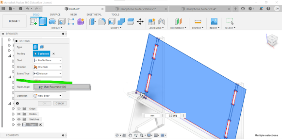
Step 26: Select the 4 faces as shown below -> In the box that appears, Type "ply"
Step 27: This is what you should see - the completed LEG 1 COMPONENT
Step 28: Now Create another Component Titled "Leg 2" (Basically, Repeat step 5)
This is what you should see:
** Before we make Leg 2, we want to make a construction plane that we can control the distance of so that we can control it based on our product
Step 29: Click 'Construct' -> 'Offset Plane'
Step 30: Click on the origin plane [because this plane doesnt move] (See the blue highlighted plane) -> in the box that appears Type '
-Deviceheight'
This is what you should see:
Step 31: Click 'Create Sketch', this is what you will see:
Step 32: Click on the offset plane (i.e. the yellow plane far away see image in Step 31) => Click on the surface (see blue highlighted surface) => Click 'P' on your keyboard => a 'Project' box pops up => Select 'Ok'
This is what you should see:
Step 33: Click 'Finish Sketch' this is what you should see:
Step 34: Click Extrude -> In the box that pops up type '-ply'
Now we have 2 legs complete!
image A
To further emphasise on the fact that this design is parametric, now i will show you that we can edit the parameters to suit our preference/resources/limitations
For e.g. If i edit the deviceheight from '145mm' to '20mm', i can change the spacing between both legs:

Image B
(compare this to the image A)
This is how we can edit our design easily by editing the numerical value specified in the fixed dimensions previously = Parametric Design
Now we will make the next component: Tray
Step 35: Repeat Step 5 to 'Create New Component' and name it 'Tray'
This is what you should see
Step 36: Click 'Create Sketch' -> select these 3 faces for each leg -> press 'P' on your keyboard -> a project box would appear -> click 'OK':
this is what you should see:
Step 37: Draw a Rectangle that encloses the projections you've done in Step 36:
Image A
Step 38: Add some collinear Restraints
Select the yellow highlighted lines -> click 'Constraints' -> Click 'Collinear'
This is what you should see:
Image B (Compare with Image A)
Step 39: Repeat Step 38 for the 2 yellow lines below
This is what you should see:
Step 40: Select the 2 yellow lines -> Click 'Sketch Dimension' -> Type 'Border'
Step 41: Repeat Step 40 for the other end
It should look like this:
Step 42: Click on the yellow highlighted 'Collinear Restraint' and delete it
Then Click 'Finish Sketch'
It should look like this:
Step 43: Click 'Extrude' -> Click everything but the centre tab on both ends (see yellow circle)
Dont click this ^
It should be done like this:
Step 44: Set the distance to be 3.175mm then click 'OK'
It should look like this:
So now we have created the third component (Tray) already. Its time to create the last component (Top)
Step 45: Repeat Step 5 -> Create new Component and name it 'Top'
It should look like this:
Step 46: Select the following faces
Step 47: Press 'P' on your keyboard -> a Project box will appear -> Select 'Ok' and this is what you should see:
Step 48: Select the back face of the tray -> Press 'P' on your keyboard -> a Project box will appear -> Select 'ok' , this is what you should see:
Step 49: Draw a Rectangle enclosing all the projections you've just done as below:
Step 50: Select these 2 yellow lines -> Click 'Constraints' -> Click 'Collinear'
This is what you should see:
Step 51: Repeat Step 50 for the 2 yellow lines below:
Step 52: Select the 2 yellow lines below -> Click Sketch Dimensions -> Type 'Border'
Repeat the same for the green lines
This is what you should see:
Then Click 'Finish Sketch'
Step 53: Click Extrude, Selecting the below faces -> in the box that appears for distance, Type 'Ply'
This is what it should look like:
We have finished all 4 components!
This is the finished product:

Reflection:
This tutorial was mainly meant to be another CAD refresher session, whereby I was tasked to recreate a handphone holder. However, i learnt something new this time around - parametric design. The purpose of this session was to allow us to experience and try out parametric design so that we could use it in our laser cutting session when we'd have to make a group parametric construction kit.
This activity is important as learning how to use parametric design was a step further in my CAD journey and its something that is useful as if we have a lack of material or wish to last minute change the sizing of our design we can do so on the spot and modify our set parameters for dimension. This session was fun as i found it more easier than the first tutorial activity and i even tried a more tougher design with many steps, having an increased confidence in using the software.
After reflecting, I used to think that CAD software is hard especially for me since I am not very tech-savvy and usually take 3x longer than an average person to be familiar with something tech related . However, after ICPD and getting exposed to Fusion 360 again, I realized that the software was fun and not as hard as i thought especially with more practice. Now I think that designing on Fusion 360 is useful and i've gained more confidence in using it that my fears of being unable to use it have been eased. So next I will implement this skill I have brushed up on for this module especially in my upcoming laser cutting practical whereby we have to design a group parametric kit and will seek to continue practicing and getting better at it in a bid to achieve one of my personal goals (See home page).


Comments
Post a Comment