Objectives:
- Designing the object (Fusion 360)
- Operating the 3D printer to print an "impossible ball in box" object
---------------------------------------------------------------------------------------------------------------
Designing the object (Fusion 360 Tutorial)
Resource: click here
These steps will show you how to create an impossible object: a 25mm cube with a 28mm ball inside it
Step 1. Create Sketch
Step 2: Create the Cube
Use Create -> Box (See yellow highlight) to make a 25mm Cube sitting on the XY plane with a corner at the origin (0,0,0) by adjusting the length, width and height dimensions to be 25mm (See blue highlights in green box) below:
Step 3: Create a Cutting Sphere
Use Create -> Sphere (See yellow highlight) then adjust the diameter dimensions of the sphere to be 32mm at the origin (See blue highlight), selecting the XY plane for it and make sure the sphere is added as a New Body (See pink highlight).
Step 4: Position Sphere for cut
a. Select Body 2 (aka the sphere) located on the left hand side panel:
b. Right click on the sphere and select "Move/Copy"
c. Adjust the 'X', 'Y', 'Z' position to be -12.50mm, 12.50mm, 12.50mm (See yellow highlight) respectively such that the Sphere is moved into the box and aligned in the center of the box:
This is what you should see:
Step 5: Cut Openings in the box
Select Modify -> Combine [yellow highlight] -> Select Body 1 (Box) as the Target body [blue highlight] -> Select Body 2 (Sphere) as the tool [pink highlight] -> Select Operation to be 'Cut' [green highlight] -> Select 'Keep Tools' as this will save some steps later [orange highlight] -> Press 'OK' to cut the box.
Step 6: Create a copy of the Sphere and reduce it to 28mm.
(Note: If we resize the sphere now, it will also change the size of the cut area because Fusion 360 has linked the Body 2 to the Cut operation applied to Body 1. So, we make a Copy of the Sphere and resize the copy. This way we don't have to go through the positioning process of Step 3.)
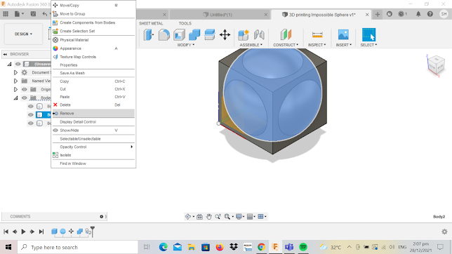
Right Click on Body 2 and select 'Copy' [See Figure 6A] -> Right Click in an open area and select 'Paste' [See Figure 6B] -> Select 'OK' [See Figure 6C] since the body is positioned is the center of the Cube the same as Body 2 -> Right Click on Body 2 and select 'Remove' [See Figure 6D] -> Select 'Modify' -> 'Press Pull' to resize Body 3 to 28mm diameter by reducing its radius by 2.00mm radius i.e. in the green box enter '-2mm' [See Figure 6E].
Figure 6A
Figure 6B
Figure 6C
Figure 6D
Figure 6E
This is what you should see:
Step 7: Connecting two bodies: Raise the Sphere
(Note: This step is used to trick the slicing software into thinking that the Box and Sphere are one object. We do this by adding a 0.1mm x 0.1mm x 12.5mm bar where the objects will be flat on the printer's base plate. But first, we need to raise the sphere up 1.5mm so that its contact point is the same as the base of the Box.)
Right click on Body 3 and select 'Move/Copy'.
To raise it (i.e. Sphere) up by 1.5mm in the Z direction, in the box under 'Z', enter '1.5mm'.
Step 8: Make a Connecting Bar - Part 1
First, hide Body 3 by clicking OFF the eye icon next to it.
Use Create -> Box and select the XY plane and Select Top view on the view gizmo. This will allow us to use a center snap that will appear in the middle of the right edge of the Box.
Step 9: Make a Connecting bar - Part 2
With this as the first corner, select 'Create' -> 'Box' [yellow highlight] and draw it such that extends to the middle of the base of the Box and adjust its position of X, Y and Z to be 12.5mm, 0.1mm and 0.1mm respectively (green highlight) . Use the Join Operation to have it connected to the Box (Pink highlight) and Select 'OK'.
Step 10: Join Everything Together
Unhide the Sphere (Body 3) -> Select 'Modify' -> Combine (Yellow highlight) -> Select 'Body 1' as the Target (green highlight) and 'Body 3' as the Tool (Blue highlight) . Unselect Keep Tools if it is still selected. Use the Join Operation (pink highlight). Select OK.
This is what you should see:
Step 11: Form Final Object
Right Click on 'Bodies' and select 'Create components from Bodies'
This will give us 'Component 1:1' :
Final Product:
Embedded Fusion f.3d file:
As the time taken to print the object was 1h 1 minute when i sliced it, it exceeds the requirements of printing within 1 hour.
So i increased the speed of the printer from 50mm/s to 100mm/s with the following printer settings:
Cura Settings
Printer: Ender 3
Rafts: No
Supports: No
Resolution: 0.2 mm
Infill Density: 15%
Wall thickness: 0.8mm
Printer Speed: 100 mm/s
Layer Height: 0.2 mm
Filament color: Orange
Filament material: PLA
Time Taken to Print: 52 minutes
It meets the requirements.
--------------------------------------------------------------------------------------------------------------
Operating the 3D Printer - Creality Ender 3
Generic Workflow:
1. Creating a printable 3D Design in Fusion360
2. Converting the 3D design into a 3D representable file
(STL or 3MF)
3. Slicing the 3D representable file (STL or 3MF) into
layers using Cura slicer software
4. Converting the layers into instructions for the 3D
printer (gcode)
5. The 3D printer creates the 3D object
So far, we have done steps 1 to 3. Steps 4 and 5 involves operating the 3D printer.
The printer we are using - Creality Ender 3 :
1. From the drawer in the base of the printer, remove the drive containing the chip. Ensure that the chip is placed in the drive (The figure below shows the chip and the drive separated).
2. Insert the drive (containing the chip) into your laptop or desktop and save the sliced cura .STL file as gcode into the drive (the file would be saved into the chip inside the drive also which would be placed inside the printer to be interpreted by the printer.)
How to save -> click the 'save to removable disk' at the bottom right hand corner of your screen in CURA (See figure below red circle).
Once done, eject the drive.
3. Remove the chip from the drive and insert it into the slot at the base of the 3D printer (See red circle)
4. Once the chip has been loaded, now we need to prepare the 3D printer.
A. From the PLA filament roll, pass it through the hole on the plastic container and through the opening hole of the 3D printer. Using the knob on the 3D printer roll it clockwise till you see the PLA Material coming out of the nozzle. This is an indication that there is a constant supply of material for printing which will not interrupt the process.
On the screen attached to the printer, select 'Prepare'
Preheat the printer bed to optimally 60 degrees celcius and the nozzle to 200 degrees celcius by navigating the screen attached to the printer
Then, select disable stepper.
C. Upload the file you've saved into the chip earlier into the printer and start printing. You should see this on your screen attached to the printer:
5. The printer starts to print your object.
Final Object:
Hero Shot:
Why this object cannot be made substractively?
Additive manufacturing is a process that adds successive layers of material to create an object, often referred to as 3D printing. Rather than adding layers, subtractive manufacturing involves removing sections of a material by machining or cutting it away for example via Laser Cutting.
In this case, the ball is a sphere which cannot be made via laser cutting as it is not a flat surface. In order for this object to work the ball must be trapped inside the box however, we cannot make the ball and box separately i.e, the box cannot be laser cut and then place the ball 3D printed into the box as the object would no longer be an 'impossible ball in box' toy anymore since one would be able to remove the ball from the box. Therefore, this object can only be made via 3D printing as it has to be made in layers as a whole in order for it to be impossible to remove the ball from the box. Therefore this object cannot be made substractively.
---------------------------------------------------------------------------------------------------------------
Reflection:
The main objective of the activity was to design (fusion 360) and print an object that cannot be substractively printed i.e. the object has to be printed in layers instead of being cut from a block or piece of material. We had to apply our earlier learnt CAD skill via Fusion 360 to design the object and then later 3D print the object.
This practical session required us to apply what we learnt during ICPD i.e. the theory of 3D printing into practice - whereby in ICPD each group had to research on a topic related to 3D printing and teach the class what they learnt from their research for example, my group researched about the various materials one can use for 3D printing and when to use them depending on the object being printed as well as the pros and cons of each material while other groups researched and taught the class about printer settings for example.
However, what was new was that we didnt know the workflow of 3D Printing an object and more about what it meant when we adjusted certain settings and how that would affect the printing process and hence the final product. Thankfully, the resources from blackboard were useful in explaining to us the workflow of 3D printing an object and how to operate the printer as well as how to adjust certain settings to obtain the desired object. I learnt that after we do Computer Aided Design via Fusion 360 we had to convert the fusion .f3d file into a .stl file, upload it into a new software CURA and adjust printer settings after which slice it and convert it into a gcode for the printer to interpret and print the object.
This activity is important for us to expose ourselves to a new skill - 3D printing and to be able to know how to independently follow the workflow from CAD to operating the printer and printing a desired object as well as to know how to adjust certain settings in CURA to get the desired product or to hasten the printing process. The activity is useful for us in our Prototyping in CPDD in term 4 as after exposing ourselves and learning this new skill - 3D Printing, we would be able to use this to make certain components of our chemical device independently also this process saves time and resources instead of having to either make it from scratch by hand or buy it. Also the material PLA used is stronger than cardboard if we prototyped it by hand thus the functionality and durability of the component for the chemical product would be better if 3D Printed.
I made an 'impossible ball in box' object as it cannot be made substractively and it was very interesting to see how the printer printed the object from scratch to the eventual product. However there were challenges I faced during the printing process. Going into W319 and facing the printer for the first time i didnt know how to operate it even though i knew it in theory, luckily there were helpful Y3 seniors present who helped me through and taught me where each component of the printer was and how to navigate through certain functions of the printer via the screen attached at the side. Also when i sliced my file, i saw that it would take me 52 minutes to print the object and i thought that within one try i would be able to successfully print the object so i was pretty relaxed as i still had another hour for buffer when i booked my slot (students are allowed to book max 2h slot for printing) however, halfway through the process, my object started breaking as it was being printed and so i had to abort the printing and start again. I tried for 3 more times and it resulted in the same thing - unsuccessful attempts. (See the figure below):
I was starting to get worried because my 2h slot was nearing completion. Thankfully, the seniors helped me through and they explained it to me it was either the filament material was weak (not my fault) or that the object wasnt sticking to the printer bed because it wasnt hot enough and thus when the printer nozzle moves to print other parts of my object as the base wasnt solid it broke. And so i tried increasing the printer bed temperature from 60 degrees to 90 degrees. It worked! All thanks to the seniors! I will be sure to continue this helpful cycle of learning by helping my juniors next year and carry on this legacy of mutual learning :)
In conclusion, I used to think that 3D Printing was tough as i had never done it before and i started losing confidence as i saw my object failing to print successfully for several times. However after help from my seniors and a positive mindset as well as after being through tougher activities like arduino programming and completing the tasks successfully, now i think that if i put my mind and put in effort in anything it only seems harder before it gets easy and hence 3D Printing isnt as tough as it seems since i've learnt alot about the process and to troubleshoot problems now. So next i will apply this skill in my CPDD prototyping phase when i design and 3D Print the compartment to hold all the electronics of my chemical device - a CO system with ventillation.


Comments
Post a Comment