Laser Cutting entry
Objectives:
- First Segment contains Notes I've taken on Laser Cutting
- Second Segment contains :
- Improved Standard Operating Procedure for using a Laser Cutter
- Processes done during the practical when operating the Laser Cutter --> ( for both individual competency test & Group parametric kit)
- Reflections
-------------------------------------------------------
Notes:
(Source- https://www.youtube.com/watch?v=t4BfQGhhbOQ , https://www.youtube.com/watch?v=p2thSkOa_Xg, https://www.youtube.com/watch?v=jDylvHraCAU + Blackboard Slides)
1) What is a CO2 Laser-Cutter?
- Laser Cutters are a machine that are controlled by a computer to cut and engrave material using a laser beam -> CO2 Laser cutter is a type of Laser cutter. Other common types are: Laser Diode, Fiber Laser
- CO2 Laser-Cutters are good generalists and provide 'good bang for your buck' i.e. cost-effective
2) How does it work?
- CO2 Laser is produced in a CO2 laser tube (a glass tube with gas sealed within, namely carbon dioxide and some nitrogen.


---------------------------------------------------------------------------------------------------------------
A: Safety
1.
Remove any foreign objects
around the neck/body to prevent getting tangled into the Machine
2.
Ensure long hair/ fringe is
tied up
3.
Lift the cover of the Laser
Cutter fully
4.
Do not put your head inside the
machine
5.
Do not slam the cover of the machine
(as the interlocking light would disappear)
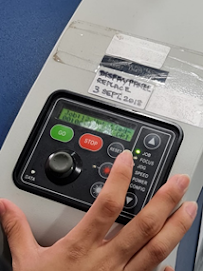
6.
Do not assume LED is spoiled,
ensure both Left and Right LED is green/on (See Figure 1)
7.
Do not lean your body on the
cover of the Laser Cutter (as it would trigger the safety interlock and
operation of the Laser Cutter would halt)
8.
Do not stare into the beam
while cutting
9.
Do not leave machine unattended
while cutting/engraving
10.
If a small fire occurs
attempt to extinguish by blowing/removing material from laser cutter *Safety
Feature: (There is a safety interlock, simply open the Laser cutter cover fully
which will aid to stop the beaming of the laser and movement of the head)
11.
If the material cannot be cut
through, stop and check - Focus lens might be dirty.
* Continued use of dirty lens will result in Cracked
Lens (See Figure 2)
12. When using the Epilog Software - Remember to on ‘Air Assist’ (if not it will result in Fire)
B. Start up
1. Turn on the air compressor (See Figure 3 and 4)
Turn on the fume extractor (See Figure 5 and 6)
*N*Note: If you are using FUSION PRO, the air compressor is built into the fume extractor so you wouldnt see an external air compressor like the one shown in figures 3 and 4 so actually, there is one less step if you use Fusion Pro machine
rerevised step: Turn on the fume extractor for FUSION PRO by pressing this button (blue circle):

3. Turn on the main laser cutter (See Figure 7)
*Note: If you are using FUSION PRO, the way you turn on the main laser cutter is different from shown in Figure 7
Revised Step: Turn the key ANTICLOCKWISE to turn on the main laser cutter as shown below:

4.
Wait until the laser cutter
completes initializing [around 1 minute] (See Figure 8)
*Note: if you are using Fusion pro machine, this step ^ is unnecessary just straight away proceed to workstation
5.
Proceed to the Workstation i.e.,
Desktop connected to Laser Cutter
C. Operation
(Using CorelDraw):
Additional step: You would need to open the CorelDraw app on the desktop before you start using it
*For Basic Features, Refer to Figure 9-12, (See Note below Figure 12 for guidance)
1.
File -> Import; Import the
DXF file (Fusion 360 File) into CorelDraw
2.
Select the Image after Imported
(See Figure 13)
3.
Click Bottom Right Corner (Pen
and Fill icon) and adjust the appropriate settings i.e. (Colour, Line weight
and Fill) for Cutting and Engraving. (See Figure 12)
4.
Once done, Press ‘Control +P’,
Print box would pop-up, and Select ‘Print’ (See Figure 14)
Instead of pressing 'Control + P', you can click the fourth icon on the top bar from the left to print also
Page
Automatically updates to Epilog Software
D. Operation (Using Epilog Software)
1.Fusion Pro
1.
Set ‘Autofocus’ ->
‘Thickness’ *Default is off (See Figure 15)
2.
On the right-hand side, it will
show the process of each object’s action which was pre-set earlier when using
CorelDraw. Click on each process’s action to check the settings again. (See
Figure 16)
*Note: Any object’s line-weight set as hairline are considered as vector and with thickness is considered as engraving
For my individual competency test, the assessor didnt want me to engrave he just wanted me to vector cut and engrave outline so to turn off the engrave function, just click "off" on the engrave process function to turn off this process.
2.Fusion M2
1.
Set ‘AutoFocus’ -> ‘On’
2.
Choose ‘Air Assist’ -> ‘On’ for
each process
(For Steps 1 & 2 See Figure 17)
3.
On the right-hand side, it will
show the process of each object’s action which was pre-set earlier when using
CorelDraw. Click on each process’s action to check the settings again. (See
Figure 18)
*Note: Any object’s line-weight set as hairline are
considered as vector and with thickness is considered as engraving
E. Material Setting
1. Load Material Library
1.
Click the ‘Folder Icon’
(See Figure 19) to Load Material Library
*Note: (See Figure 20 for
view of Loaded Material Library)
2.
Once Material Library has
loaded, choose which material to be used for cutting/engraving. Do it for both Processes.
Then Click ‘Import’ (See Figure 21)
3.
For Engraving, Select the
Engraving Tab and enter the thickness of the material chosen. (See Figure
22)
*Note: To be able to select a material,
you would need to know its thickness so measure its thickness using a Vernier
caliper first
4.
For Cutting, Select the Vector
Tab and enter the thickness of the material chosen. [i.e. Repeat Step 3]
5.
Always Check that ‘Air
Assist’ is turned on for FUSION M2 Machine (See Figure 22 – Blue Circle)
*Refer to Figure 23 for Final
Adjustments for Machine in this step.
Additional step: Remember to ask the TE for the speed and power information which you would need to input in also at this juncture
F. Positioning (*If required)
1.Fusion Pro
1 Adjust the position of the material using the build in camera in fusion Pro. (See Figure 24)
2.Fusion M2
*There is no Built-in camera
1)
Adjust the material using mouse tool on the left
bar and adjust base on the location of 2 ruler on the top and left. (See
Figure 25)
Additional step/tips: [Note, to be done on Coreldraw]
- if you want to reposition an object with many lines, you can't simply click the cursor icon on the left side bar and drag/move the object because that would only drag the selected lines but the other internal lines of the object which wasnt selected wouldnt be repositioned
* So what to do? => Select the entire object -> Right Click -> select Group
Now you can reposition it and the changes would be uniform throughout all the lines of the object as it is treated as one connected object now
Figures to guide you:
The problem:


- In the midst of repositioning your object, you realise there are some lines within your drawing which arent supposed to be there => Use "Virtual segment delete function"


To solve the problem, we managed to delete the circle line outside of the star since it was not grouped to the star itself. However, to get rid of the lines forming the pentagon in the star which also obstructs the slot, we had to use the “virtual segment Delete’ function [see blue circle]. Then we used the cursor and clicked on those lines we wanted to remove to eventually give us the intended shape of the star component
G. Print
Once done, Click on “PRINT” to send file to Laser cutter. It will not cut immediately but to show up on the LCD screen instead. (See Figure 26)
1.Fusion Pro: To cut, check file name and estimated time to cut on the LCD touch screen. Once confirm, press the “play button” (See Figure 27)
2.Fusion M2: To cut, check file name and estimated time to cut on the LCD touch screen. Once confirm, press the “Go button” (See Figure 28)
Wait for 1 minute
after completed printing
H. Shut Down: (Reverse of Start up)
Ammendment step: *Note, if you are using Fusion Pro machine, See section B "start-up"'s red steps and do them in reverse order to shut down
1.
Turn off the main laser cutter (See
Figure 7)
2.
Turn off the fume extractor (See
Figure 5 and 6)
3.
Turn off the air compressor (See
Figure 3 and 4)
I: Appendix
1.
Safety:


Figure 2: See Cracked Lens
2. Start-up:

Figure 3: Air Compressor


Figure 5: Perspective of where Fume Extractor is Located
– Downwards, Left-Hand side of Machine (see arrow)


Figure 12: (3): Bottom Bar Icons and Descriptions
**Note: Vector Cut refers to outline of Shape to be cut, Engrave refers to fill of shape to be engraved, Engrave Etch/Score refers to outline of shape to be engraved

Figure 13: Selecting Drawing

4. (Using Epilogue Software)

Figure 15

Figure 16

Figure 17

Figure 18
5. Machine Setting

Figure 19: Folder Icon which loads Material Library


---------------------------------------------------------------------------------------------------------------
Referring to SOP we created, we used the FUSION PRO MACHINE and followed all the standard steps for start-up.
Below shows the processes for CorelDraw, Epilogue Software and Cutting:
a. A. CorelDraw
a.

à
Importing DXF fusion files of 5 objects

à Imported 5 objects (Although this image clearly shows the scale at which our objects were and would be cut eventually, we didn’t realise it at this point and continued to proceed instead of adjusting their dimensions which is why eventually our first batch had the 5 objects cut very small)
We then changed the colour of the outline of the 5 objects to red and changed the line weight to hairline after which we proceeded to click print. Thereafter proceeding to the epilogue software
b. B. Epilogue
Software


We then clicked
Print
c.
Cutting
à After waiting for the screen to confirm
the job title and duration for printing, we Pressed ‘Go’ which commenced the
Cutting of our 5 objects


à This was our final product. At this
point, we realized we did not set the proper dimension for our objects to be
cut as it was too small which was why we had to redo the process.
2nd Batch Laser-Cutting Process
a.
CorelDraw

à We changed the
dimension to scale up our product (one example from the 5 components to which
we did the same) However, we halfed our actual Fusion 360 Dimensions as we felt
that the components would be too large which is why the dimensions they would
be cut to would be half of our desired dimensions in Fusion 360.

à As we scaled up our components (the large circle for example), we realised that our lines were not grouped which was why the slots created on the components shifted away, leaving us with drawings that didn’t match our Fusion 360 designs.


|
à Another Problem we faced as we
were scaling up the components was that we had unnecessary lines in the
reflected drawing on CorelDraw. For example as shown in this figure, for
the star component, on the Fusion 360 application on the laptop, it shows
our desired design however, on Coreldraw, there is an unnecessary circle
and lines inside the star which was obstructing the slot. If we did not
resolve this, the shape would be cut as per how it looks like in CorelDraw
which would firstly, not suit our intended aesthetic appeal and secondly,
not fit into the other components since the slot had been obstructed.  |
è To solve the problem, we managed to
delete the circle line outside of the star since it was not grouped to the star
itself. However, to get rid of the lines forming the pentagon in the star which
also obstructs the slot, we had to use the “virtual segment Delete’ function
[see blue circle]. Then we used the cursor and clicked on those lines we wanted
to remove to eventually give us the intended shape of the star component

Then we set the correct colour and line weight settings for the corrected components and click ‘Print’ which will go into Epilogue Software
b. b. Epilogue
Software

c. C. Cutting


Our batch 2 components, scaled up à Removal in process
Conclusion: Figure of some of Our Final Components:

Figure showing difference of width of slots accounting for misfit

(Slot of small circle is 3mm) (Slot of square base is 1.7mm)
è Our final cut Components were too small and could not fit together as a parametric kit. This was because we decided to half our desired dimension from Fusion 360 and when we did it, we did not use the ‘Group’ function to select all the components and change their dimensions uniformly which was why the width of the slots of some components differed and could not have a proper fit.
Thus,
the following day after our Practical [Friday, 29/10], we had to do a Batch 3.
Batch 3 – Successful Christmas Tree


è
For this final Batch, we followed all the process of Batch 2 however, for the dimensions aspect, we inputted the exact same desired Dimensions we used in Fusion 360 when designing the CAD drawing of every component which ensured that the kerf was accounted for, the scale was accurate and the parametric construction fits.
Hero Shot

Reflection
This practical is linked to this week’s tutorial in which we were introduced to Parametric Drawing on Fusion 360 which essentially is a computer aided design (CAD) software design tool that saves time as it eliminates the need to constantly redraw a design every time one of the design’s dimensions changes.
As a group, we were tasked to create, and laser cut a Parametric construction kit. We had two main parts to this practical – the first being applying our knowledge of Parametric Drawing on Fusion 360 to create the construction kit and the second being correctly operating a Laser Cutter. The main skill assessed during this practical was the ability to operate the Laser Cutter correctly and safely from start-up, using CorelDraw, Epilogue Software, Cutting/Engraving to shut down, which was assessed individually.
Personally I felt extremely intimidated by the individual competency test, however i knew it was a very important aspect of this practical because it ensured that everyone of us knew how to use a Laser cutter correctly and safely. It also gave me more confidence and a good foundation of knowing how to use the laser cutter as I had no choice but to physically use it as part of the test – and if this did not take place, by merely watching video tutorials of seeing how others operate it would not be as effective. During the test itself my assessor - Mr Walter also gave me good tips and reminders of other features which we were not assessed on for example, the "Virtual Segment Delete Function" which helps to get rid of unwanted lines in my sketch if i imported it from Fusion but somehow it has these unnecessary lines which would affect the final shape that would be cut. I probably wouldnt have gotten such tips/advice if we did not have this test or rather a one-on-one experience with a trained coach.
I also felt that the fact that we had to create our own SOP was one of the most important aspects of this practical because firstly it meant that we weren't being spoon-fed as the lecturers wanted us to take our own initiative and figure out how to operate a laser cutter on our own after giving us some guidance via the lecture slides prepared by the fablab coaches and the video tutorials whereby we could watch demonstrations. Secondly, only until we interpret the resource materials and visualise ourselves using it and create our own instruction manual then only would we have truly internalized how to operate the laser cutter effectively and safely instead of browsing thru steps printed on a sheet of paper for us and blindly following it. No doubt completing it and submitting it on time was tough and tedious because we only had 2 days before our practical after we had been briefed about it on our tutorial but still, it allowed me to internalise everything and this knowledge rooted in me would serve me well in the later periods when i have to operate the cutter in the prototyping phase should my group want to utilize laser cutting.
Comparing to Cardboard Prototyping which I learnt in Semester 1, it is an important and very useful skill to be able to Laser cut as Laser cutting saves so much time when building a prototype (although a limitation would be that Laser cutting can only be used to cut flat surfaces). Moreover, the final aesthetic is consistent in terms of texture and dimensions as well as cleaner and more appealing. I would also be able to envision the final product’s look and adjust the dimensions on the spot or change the shapes/drawing on the spot using the CorelDraw software in the event if i am unsatisfied of how it would turn out – something which is not possible when Cardboard Prototyping as one would only know the final look after completing it. This would be especially handy when I would have to build a prototype for my group project in CP5070.
Ultimately,
after reflecting about my experience in this practical, I used to think that Laser cutting is extremely complex because the term itself ‘Laser
Cutting’ sounded very high-tech and foreign which i have never been exposed to. I also used to not be able to see
the link between such a skill and the DCHE course. However, now I think that it is
not a very difficult skill and does not sound as intimidating as before since I contributed extensively to developing my group's own procedure which was extremely useful in deepening my understanding of operating the laser cutter as I had to envision how to use it
as I developed the SOP. Moreover the experience of using it on my own when
cutting the Parametric Construction designs made me more confident and familiarized. I also realized the entire operation of the laser cutter to eventually cut our
product took less than half an hour which would take 3-4 times more if we would
have prototyped it using mere cardboard. The functionality and aesthetic of the
final product was more optimal as well. As I already knew how important
prototyping is from ICPD in semester 1, with a more easier, faster and
efficient method which I have learnt now, it further reinforced this. So next, I will be sure to use Laser Cutting for my group's final prototype of our CP5070
project instead of Cardboard Prototyping when i contribute to the prototyping phase of my group.
Problems encountered and how we resolved them:.
1. 1. In our Batch 1, we forgot
to adjust the dimension of the drawings according to our desired dimensions and
left it as it was on default i.e. 5mm which was why when it got laser cut it
came out to be very small and it was at this point that we realized this
mistake. To resolve it, we had to do a second batch and re-cut so when we went
back onto CorelDraw interface, we were sure to adjust the dimension and scale
up the size of our components. However, after discussing as a group, we decided
to half our desired dimensions (i.e. the dimensions used to draw in Fusion 360).
Eventually, the components were printed at a bigger size than batch 1.
2. 2. For Batch 2, as we
adjusted our dimensions to scale up our components in an attempt to resolve the
problem we encountered in Batch 1 (i.e. the components were cut extremely
small), the problem we faced was the lines in our drawings (for example, lines
in the circle used to create slots) went all over the place leaving the circle
component to look like a mere circle. This was a problem we had to fix if not
the way the component would look like when it would be cut later on would just
be a mere circle with no slots and so it would not fit the construction. To
resolve this problem, we used the “Virtual Segment Delete Function” which was a
function whereby when one clicks on a line they wish to remove with their cursor,
it would be removed. And so eventually, we got the shape we wanted our
component to look like when it was cut.
3. 3. For Batch 2, despite
doing the above listed 2 solutions to fix the problems we encountered, the end
result was still problematic i.e. the size was although bigger than batch 1 but
it was still relatively small for a construction kit moreover, as we scaled up the
dimension for our components, yet decided to scale it half of the desired
dimension though still larger than batch 1, when we did so, we didn’t account
for kerf and we did not uniformly half the scale for all components which was
why some components had discrepancies in the thickness of their slots i.e. as
the acrylic we used was 5mm, the thickness of all slots should be around 3mm when
halved however after measuring using a vernier caliper, some had thickness of
1.7mm and some was 3mm which was why the components had a loose fit for batch 2
and it was yet again unsuccessful. To resolve this problem, when we returned to
school to make batch 3, not only did we follow our desired dimensions (i.e. the
one in Fusion 360 used to design the CAD drawings of all components) exactly instead
of halving it but we also accounted for kerf. Thus, the end result was successful
with a good size of components with good fit.
Comments
Post a Comment