Project Development
Template for Project Development Entry
1.
Our team Chemical
Device
In this section,
you will briefly describe your team chemical device.
What it is. What
problems will the chemical device solve? And provide a hand sketch of the
chemical device.
· Team Chemical Device: Automated
CO Monitoring & Ventilation System
· Background:
Around 2.6
billion people still cook using solid fuels (such as wood, crop wastes,
charcoal, coal and dung) and kerosene in open fires and inefficient stoves.
Most of these people are poor and live in low- and middle-income countries.
These cooking practices are inefficient and use fuels and technologies that
produce high levels of household air pollution with a range of health-damaging
pollutants, including small soot particles that penetrate deep into the lungs.
In poorly ventilated dwellings, indoor smoke can be 100 times higher than
acceptable levels for fine particles. Household air pollution (HAP), which
results from incomplete combustion of the solid fuels. à
Incomplete Combustion chemical equation: Fuel + O2 -> CO + Stack gases. 7.5
million people die from HAP annually most of them originating from lower income
countries.

Figure 1: Statistics on Deaths due to Household
Air Pollution
· What is currently being
done to help:
For example: United Nations and
World Health Organization (WHO)
-
Advocacy and Educational Efforts
Working to integrate guidance and
resources for supporting clean household energy into global health initiatives
and decision-support tools, such as the Global Action Plan for Pneumonia and
Diarrheal Disease (GAPPD).
Advocacy can help increase
awareness of the importance of providing and scaling up of cleaner household
energy as a core preventive public health measure.
-
Providing Technical Support to health-promoting
household fuels and technologies
· Challenge despite
efforts:
1) Takes
a long time for solution to be developed and implemented in the process as such
organizations are working towards large-scaled, long-term solutions. But in the
meanwhile, it means more deaths every day.
2) Changing
rural people’s attitude and effectiveness of solution:
Programs to introduce clean
cookstoves cannot simply assume that these so-called improved stoves will be
accepted by the rural household or that they will benefit health. The open
fires these rural people use to cook has deep rooted connections to their
cultures and hence carries the risk that implementation of greener cooking
methods will not improve health since the rural people might not be open to change.
3) Affordability
Even if these organizations do
implement greener alternatives, the daunting task ahead is to ensure it is affordable
and scalable to hundreds of millions of households who already face financial worries.
Resources:
https://www.ncbi.nlm.nih.gov/pmc/articles/PMC3672215/
https://borgenproject.org/cooking-fuel-in-developing-countries/
è Hence, this explains why our role is so
important.
·
THE ISSUE WE WANT TO SOLVE:
Solid
fuel use is closely linked to poverty and clean cooking technologies must be
affordable and desirable to families with limited and insecure incomes.
·
PROBLEM STATEMENT:
What
sustainable and/or affordable solution can we provide to prevent health
consequences arising from ineffective cooking methods i.e. household air
pollution to lower-income rural families whilst allowing them to hold onto
their beliefs?
· How our prototype
solves the Issue?
- Provides
a short term, affordable solution (refer to our
design specification table, total cost of prototype < $150, cheaper compared
to initiatives governments/organizations roll out which costs millions of
dollars and also take long to implement)
- Complete
autonomy of use for people (rural people won’t feel
restricted that they have to follow rules when using our prototype, unlike when
policies are implemented.)
- Sense
of independence and freedom for users
- A
catalyst to drive change
(rural
people might still want to use fuel to cook because of ties it has to their culture
so we can’t expect their behavior to change overnight hence the CO monitoring
and ventilation system i.e. our prototype, complements their current behaviors
and acts as a catalyst for change to cleaner sources of fuel à when they see how many times the ventilation had been triggered, we
hope they become more aware of how unsafe their current cooking method is and
be open to change)
-
EFFECTIVE
(It can effectively detect unsafe levels of CO, reflect
it on the LCD screen for the user to see and also provides a solution i.e.,
ventilation to return back environment to safety for user.)
·
HAND SKETCH OF FINAL CHEMICAL DEVICE:
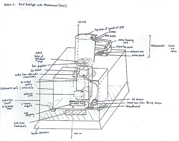
Figure 2: Final Sketch
of Chemical Device
2.
Team Planning, allocation,
and execution
In this section,
list down your team member's name.
Team Members:
Serena – Chief Executive Officer (CEO)/Leader
Kenny – Chief Financial Officer
Kai Rong – Chief Operating Officer
Jerome – Chief Safety Officer
Show the finalized BOM (BILL OF MATERIALS) table.

Show the finalized Gantt chart (planned and actual) and the task allocation for each
team member.
PLANNED GANTT CHART


- Serena and Jerome are in charge of CAD fusion while Kai Rong and Kenny are in charge of the Arduino Programming
- The team then comes together to 3D print, laser cut then assemble and prototype testing
3.
Design and Build
Process
In this section,
provide documentation of the design and build process.
Design
Process:
· Evolution of Idea to
Final Prototype (Using Hand Sketches & CAD Screenshots)
OUR JOURNEY

Figure 3: Our Journey
1.
Our Initial Idea
(Brainstorming & Ideation)
In the Figure below, the long
rectangular box was supposed to be a casing for the electronics i.e. Arduino
Board, Breadboard wiring, sensor (for monitoring of CO), LCD display etc,
whereby we would hotwire and connect a portable fan we would buy from external
sources e.g. Lazada to this electronic casing for the ventilation aspect of the
prototype.

Figure 4: Initial Idea
Sketch
However, after going through the idea refinement
processes such as TRIZ, we realized we had to refine our initial idea as it was
not effective.
2.
Our Refined Idea (Idea
Refinement Processes)
In Figure 4, our initial idea, we realized
that our chemical device was placed in the surroundings itself this was ineffective
because it means that even after the fan blows the excess CO in order to
restore the CO level to be safe, this blown CO would not be redirected elsewhere
because it would just be blown back into the same surrounding air i.e. we had
not reduced the level of CO in the surroundings after all.
Hence, after going through TRIZ,
we came to realize that to refine our idea further, we had to change the local
quality of the air. (See Figure 5: Conclusions from TRIZ).
Hence, in order to change the
local quality of the air, we knew it meant the excess CO had to be directed out
of the surroundings. Hence we decided that our chemical produce had to be
placed in an enclosed space like a vent whereby it should have an inlet and
outlet opening for the air to enter and exit. This is so
that when
CO detected by the sensor exceeds the limit the fan blows out the excess CO and
as the outlet hole is the only exit route, it would be directed out and escape
externally , helping
to change the local air quality in the box to be of safe levels of CO.

Figure 5: Conclusions
from TRIZ

Figure 6: Refined Idea Sketch
(After Idea Refinement Processes)
3.
Adjusted Concept (Planning
Phase + Consideration of BOM)
As we entered the Planning phase whereby we
discussed who would take charge of which components of the device and
eventually build that as well as planning for our budget in our Bill of
Materials (BOM), we realized that a way to further reduce the cost in our BOM was
to not buy a portable fan from Lazada but instead make use of the resources and
skills we had i.e. Arduino Program a DC motor with an attached fan propeller to
rotate as a replacement to the fan. This saved us approximately $30 and
also the fact that we didn’t have to lag behind our progress later on due to
waiting on delivery time also made us a high performing team. Another adjustment
we made was the design for the electronics housing case. Initially the design
in the earlier 2 sketches showed the electronics housing unit to be long but
short in terms of height because we thought we could bend the wires and save
material. However after measuring the dimensions
as we prepared to enter the building stage, we realized we couldn’t bend the
wires and hence we had to build a smaller box inside of the larger box (vent)
to act as the electronics housing.


4) Improved Concept (After feedback
from Dr Noel)
At
this point, we were confident of our Adjusted Concept and hence had already
dived into the Computer Aided Design (via Fusion) part. However, when we had a
Microsoft Teams consultation with Dr Noel, he gave us some feedback (in the paraphrased
quotes) which prompted us to change our entire design i.e.
-
“Think about the fact that your device is going to be
used as a kitchen fumehood. How should the airflow be in that case?”
-
“Would the
current orientation provide sufficient negative suction for the airflow in and
out?”
-
“If you place your DC motor this way i.e. simply rested
on a stand, wouldn’t it vibrate and wouldn’t that affect the performance of
ventilation?”
-
“I currently cant visualize it to be a fumehood, how
will you change your design to replicate one? Look at the resources in DCHE
blog”
Hence,
we improved our design by firstly changing the orientation to be vertical
I.e. the airflow inlet and outlet would be vertical now instead of horizontal
earlier. This was because in order for our prototype to solve the issue we
wanted to, it would be used as an affordable kitchen fumehood hence, the air
from the cooking would rise and travel upwards vertically. This also meant that
the fan which provides ventilation to blow out excess CO would now be placed
vertically facing upwards. This was to ensure we could create negative
suction pressure for the air to be drawn in and later CO exit out. Hence to
provide sufficient inlet air flow as well as for the general appeal to look like
a kitchen fumehood, we created a bottom hood like structure. To hold in
place the fan connected to the DC motor to ensure the ventilation provided is
efficient, we also decided to make a DC motor casing which would also act as
a stand to allow the fan to prop out of the electronic casing as well. The
air would enter from the ghood vertically upwards and exit through the top hole
of the cylindrical pipe. There is a gap between the inner and outer boxes as
the inner box is completely sealed with just a hole for the fan to be
protruding out of it but still in the outer box.


Figure 8: Improved Idea Sketch
5) Final Prototype (with Mechanism)
We
then decided to add a Lever Mechanism which would be operated using a servo
motor. The purpose of this is to make the air flow exiting the device to be
automated. For our earlier Improved Product, the plan was for the cylindrical
pipe to always be opened however we realized this meant that there could be
clean air lost. And for already poorly ventilated spaces where our target
audience lives this could be more harm than good. Hence to prevent this it
meant that our air outlet pathway should only be open when it needs to i.e.
when CO levels are unsafe. Hence to make this automated, there will be a cap on
the cylindrical pipe which would be connected by a lever. When CO levels are unsafe
and the fan turns on, the servo would also turn on to push the lever and open
the cap as the servo turns 180 degrees angle.

Figure 9: Final Chemical Device
(With Mechanism)


Figure 9b: Improved Prototype Cross-Sectional View


Build
Process:
Part 1. Design and Build of Outer Box (done by ME).
Documentation for task 1.
1. Create a set of Parameters to make the design Parametric


6:


This is what your sketch should look like at this point:

8. Create a new component "Right Side Box"

9. Create Sketch of a Square face 200mm (Parameter: Box Height) by 200mm (Parameter: Box Width)

10: Extrude Sketch by 5mm (Parameter: material thickness)

11. Create new component "Box Back Face"


13. Extrude sketch by 5mm (Parameter: Material Thickness)

14. Create new component "Box Top Face (fan side)"

15. Create a sketch of a large 200mm (Parameter: Box Length) by 200mm (Box width) square

16. Extrude by 5mm (parameter: Material thickness)

Now we are going to start designing the Hood like structure at the bottom

18: Sketch a Trapezium from the front LCD face with 50mm slant height

19: Extrude the trapezium by 5mm (Parameter: Material thickness)

20: Create new component "Opposite LCD side Hood"


22: Repeat Step 19 and 4 - Extrude the trapezium by 5mm (Parameter: Material thickness)

This is what your CAD should look like at this point:


24: Sketch a slanted rectangle 200mm (Parameter: Box Width) by 50mm slant height
First, click CONSTRUCT -> PLANE AT ANGLE -> ENTER 140 DEGREES

25: Extrude the face 5mm (Parameter: Material thickness)

26: Repeat steps 23 through 25 for the "Right side hood"
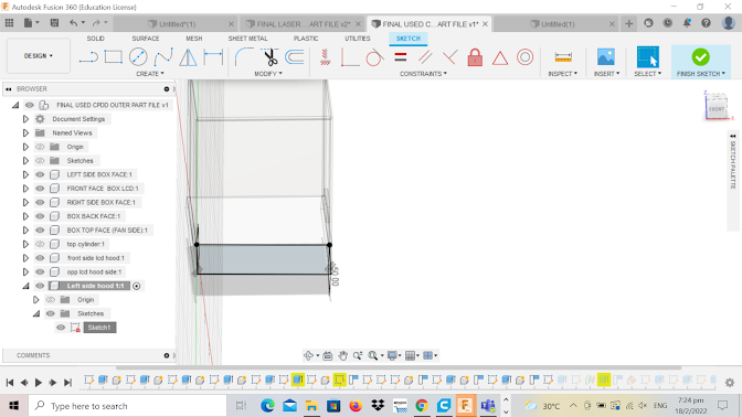
- Create new component "Left Side hood"


27: Create new component "Cylindrical Pipe" --> Draw a 50mm diameter circle --> Use Dimension tool and position the centre of the circle 55mm from base edge of top face --> extrude to 100mm --> inside draw a 45mm circle --> (-) extrude the inner circle all the way through to create the hole
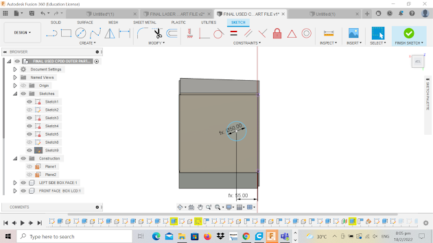


OVERALL CAD SKETCH:

EMBEDDED FILE:
Hero shot for
task 1.

Me (scoring cardboard for the cylindrical pipe) with the laser cut pieces for the outer box laid on the table.
Building process:
2) Saved the file as DXF


5) Scoring for the top cylinder


Part 2. Design and Build of DC Motor Casing (done by ME).
Documentation for task 2.
1. Create parameters to make the entire design parametric


So its hard to tell if the shell tool worked properly so to check, select 'Inspect' tool from the top, then 'Section Analysis' and select any side and drag inwards. If you see the cuboid is hollow, then it worked!

5. Create a plane to split the box into half


7. Creating Hinge of the box

B) Zoom into the middle part of the body, draw a line 3mm from the middle of the body, create 3 circles (doesnt matter the diameter just roughly sketch 3 circles) from the end of this line


I) Select "Chain faces" and "New Body" for operation like so:


We have also created the bottom hinge


Draw another rectangle for the hinge gaps like this one we've just drawn above this just drawn rectangle, 5.5mm by GAP parameter for width


Select all the rectangles and for the "mirror line" -> Select the construction line then click 'OK" like so:


N) However there are some bodies we need to remove if not the hinge wouldnt work so..


O) Adding a As Built-Joint so that we can open and close the case


9) Creating the platform for the dc motor to rest on when in the case


10) Creating a side hole for wires connecting to DC Motor to come out of casing so that they can be connected to the electronics

It should look like this:


Hero shot for
task 2.


Print Time: 2.5 hours


Part 3. Design and Build of Inner Box (done by Jerome).
Part 4. Design and Build of L brace (done by Jerome).
Part 5. Arduino Programming of DC motor, Sensor and lcd (done by Serena).
Documentation for task 5:
Code for our product which uses the IF Else function to program such that when CO level is more than 9pmm, the message will display saying CO-unsafe Fan On and the fan would also be switched on
#include <MQ2.h> #include <Wire.h> #include <LiquidCrystal_I2C.h> LiquidCrystal_I2C lcd(0x27, 16, 2); // CHANGE 0X3F TO 0X27 AS LCD ADDRESS int Analog_Input = A0; int co; int dc_motor = 13 ; MQ2 mq2(Analog_Input);
void setup() { Serial.begin(9600); lcd.begin(); lcd.backlight(); mq2.begin(); pinMode(Analog_Input, INPUT); pinMode(13, OUTPUT); } void loop() { float* values = mq2.read(true); //set it false if you don't want to print the values in the Serial //co = values[1]; co = mq2.readCO(); lcd.setCursor(0, 0); lcd.print(" CO:"); lcd.print(co); lcd.print(" PPM"); if(co >= 9) { digitalWrite(13,HIGH); lcd.setCursor(0,1); lcd.print("CO-Unsafe Fan on"); // Print a message to the LCD. } else { digitalWrite(13, LOW); lcd.setCursor(0,1); lcd.print("CO-Safe Fan off"); // Print a message to the LCD. } } |
Since we learnt about the use of Tinkercad Simulation, I decided to try out programming of the product in Tinkercad as compared to just heading blinding into programming it.
I was able to program the CO system in Tinkercad, when there is CO, the DC-motor would start spinning.
So me and kenny tried to connect and program the lcd, Co sensor following the Tinkercad Simulation, however, it did not work as the LCD display does not light up.
Then we went online and found a helpful video that showed how to connect a LCD display and MQ2 CO sensor to arduino. The video also showed us a sample code of measuring CO, LPG and Smoke in the air then displaying it on the LCD display. From the video we were also able to get the library for MQ2. https://www.youtube.com/watch?v=MMUsPS5HUYA
Following the video, we were able to connect the LCD display and the CO sensor as in the serial monitor we were able to see the readings of CO. From the sample code, I removed the codes for LPG and smoke since they are not needed in our CO- product. By testing the code, I was able to realised that to display a message on the lCD display, I could use the function lcd.print(message) to print the message I want it to say as well as lcd.setCursor(0,0) to set the position of where the message will be printed out on the LCD.
Since we were programming it in school and was not allowed to burn in school, we tried testing by letting the fan to be switched on when CO level was low (<9ppm). But after connect the dc-motor, the dc-motor did not spin. After some thinking, we realised our mistake as we had forgotten that we needed a transistor and resistor. Thankfully we documented programming a dc-motor under the Arduino Programming task, so we were able to follow how to connect the dc-motor. Then the dc-motor was spinning.
For the coding, I tried using the IF..Else function from programmable button such that if CO is high (>9ppm) it would perform a function or else perform another function. In the first code, the problem encountered was that when the fan switches on, the LCD display would then switched off. The issue was that the code that measures the CO and displays it on the LCD highlighted in yellow was in the void setup, so when the action occurs in the void loop, the LCD does not display.
#include <Wire.h> #include <LiquidCrystal_I2C.h> LiquidCrystal_I2C lcd(0x27, 16, 2); // CHANGE 0X3F TO 0X27 AS LCD ADDRESS int Analog_Input = A0; int co; int dc_motor = 13 ; MQ2 mq2(Analog_Input); void setup() { Serial.begin(9600); lcd.begin(); lcd.backlight(); mq2.begin(); pinMode(Analog_Input, INPUT); pinMode(13, OUTPUT); float* values = mq2.read(true); //set it false if you don't want to print the values in the Serial //co = values[1]; co = mq2.readCO(); lcd.setCursor(0, 0); lcd.print(" CO:"); lcd.print(co); lcd.print(" PPM"); } void loop() { if(Analog_Input >= 9) { digitalWrite(13,HIGH); lcd.setCursor(0,1); lcd.print("CO-Unsafe Fan on"); // Print a message to the LCD. } else { digitalWrite(13, LOW); lcd.setCursor(0,1); lcd.print("CO-Safe Fan off"); // Print a message to the LCD. } } |
Then for my second code, I tried to separate the fan switching on/off and LCD display message into 2 If..else function (highlighted in green). But this caused the dc-motor to switch on and off every few seconds switching with displaying the LCD message. The problem is that it had to be under 1 if else function if not there will be two seperate commands interchanging at an interval.
#include <Wire.h> #include <LiquidCrystal_I2C.h> LiquidCrystal_I2C lcd(0x27, 16, 2); // CHANGE 0X3F TO 0X27 AS LCD ADDRESS int Analog_Input = A0; int co; int dc_motor = 13 ; MQ2 mq2(Analog_Input); void setup() { Serial.begin(9600); lcd.begin(); lcd.backlight(); mq2.begin(); pinMode(Analog_Input, INPUT); pinMode(13, OUTPUT); float* values = mq2.read(true); //set it false if you don't want to print the values in the Serial //co = values[1]; co = mq2.readCO(); lcd.setCursor(0, 0); lcd.print(" CO:"); lcd.print(co); lcd.print(" PPM"); } void loop() { if(Analog_Input >= 9) { digitalWrite(13,HIGH); } else { digitalWrite(13, LOW); if(Analog_Input >= 9) lcd.setCursor(0,1); lcd.print("CO-Unsafe Fan on"); // Print a message to the LCD. } else { lcd.setCursor(0,1); lcd.print("CO-Safe Fan off"); // Print a message to the LCD. } } |
Then I redid the code again, this time I placed the measurement of CO and display message (highlighted in yellow) in the void loop such that it would be performed together with the If...else function keeping the If..else from the first code (highlighted in green). I also changed the input from analog_input to co (highlighted in cyan) to ensure that my input was the co measurement as I thought that the input might be a problem. To my delight, we code was successful in working including when testing with actual burning of CO.
#include <MQ2.h> #include <Wire.h> #include <LiquidCrystal_I2C.h> LiquidCrystal_I2C lcd(0x27, 16, 2); // CHANGE 0X3F TO 0X27 AS LCD ADDRESS int Analog_Input = A0; int co; int dc_motor = 13 ; MQ2 mq2(Analog_Input); void setup() { Serial.begin(9600); lcd.begin(); lcd.backlight(); mq2.begin(); pinMode(Analog_Input, INPUT); pinMode(13, OUTPUT); } void loop() { float* values = mq2.read(true); //set it false if you don't want to print the values in the Serial //co = values[1]; co = mq2.readCO(); lcd.setCursor(0, 0); lcd.print(" CO:"); lcd.print(co); lcd.print(" PPM"); if(co >= 9) { digitalWrite(13,HIGH); lcd.setCursor(0,1); lcd.print("CO-Unsafe Fan on"); // Print a message to the LCD. } else { digitalWrite(13, LOW); lcd.setCursor(0,1); lcd.print("CO-Safe Fan off"); // Print a message to the LCD. } } |
Part 6. Programming of Servo Motor & Build of Mechanism (done by Kai Rong & Kenny).
Part 7: Integration of all parts and electronics (done by Serena)
For integration of all the parts, we need to insert all the files into a single file and to do that, save all different files. To access the files, open an empty file (insert pic)

and click on the left icon which shows all the saved files (insert pic)

To insert the file you want, right click on the file and there will be an insert option available (insert pic).

Make adjustments needed and repeat for other files (insert pic for final file)

Interconnection of parts

Air will travel upwards towards the vent of the chemical device from the bottom of the chemical device when someone is cooking, and fumes are produced from the solid fuel.
CO sensor is programmed so that when it senses a certain CO level it will start the D.C moto and the fan will start to spin and since there is negative air pressure, the air is sucked towards the fan from the bottom side and is blown out to the top side.
In the meantime, the LCD will also display the amount of CO present so that users are aware of the amount and will know when the process will stop.
The servo moto will also start to move the cover of the tube to allow air flow out of the device.
The unwanted CO will be blown through the tube and away from the direction of the user minimizing the amount of CO inhaled
When the CO is blown out the sensor will sense that the CO is at an acceptable level and the servo moto is programmed to close the opening of the tube to ensure nothing could drop into or enter the chemical device that could potentially damage the electronics or the fan.
If you can tell, everything starts with the CO sensor sensing CO beyond the acceptable level and the chemical device will start to operate coherently and smoothly.
Embed the finalized fusion 360 design files.
Part 8: Assembling of FINAL Prototype (done by EVERYONE)
Documentation for assembling.
The team went to W319 to assemble our product using the acrylic glue (chloroform) where we taught how to properly handle and use the glue by Dr Noel. We had to switch on the fume hood when using the acrylic glue then we had to use a needle syringe to inject the glue where when injecting the glue, the glue can be seen flowing throught the gaps when shined with a flash light. Before gluing, we need to assemble the product with tapes to shape it in the way we want. After assembling the product, with Ms Serene's permission, we were allowed to leave our product over the weekend before collecting in on Monday to allow the glue to strengthen as we were afraid that the product might fall apart on the way back home.

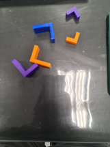
The team came together to 3D print parts like L-brace to support the inner box and the Dc-motor case


Hero shot for assembled
prototype.

Part 9: Prototype Testing, taking of video (done by Kai Rong)
Part 10: Presentation
Link to presentation file : LINK
Link
to vid of product: LINK
4.
Problems and
solutions
In this section
describe the problems encountered in the design and build process and how the team
solved them.
Problems on Programming
-
Programming in Tinkercad Simulation works but was not
able to be implemented (LCD display does not light up)
-
Solution: Found a video that showcase how to connect CO
sensor and LCD display to Arduino
-
Coding: When the fan is switched on, LCD display turns
off (LCD should be on at all time to show CO reading); When CO level is high >9ppm,
fan switches on and off every few seconds (Fan should be on continuously when
reading of CO is high)
-
Solution: Used a mix of programmable button (IF…ELSE
function) and servo (poswrite180o) codes.
Problems on Prototype 1 (based on
Sketch 4)
|
Problems |
Solution |
|
- Dimension of the
laser cut parts Ø Did not take into
consideration of excess length for power supply cable in the box Ø Assembling of walls were
uneven Ø LCD display and CO
sensor screw holes were not aligned
|
• Proper
planning and measurement of all parts taking into consideration of necessary
excess length • Power
supply need not be in the box – Cut a hole through the walls for the wire to
pass through
|
|
- Assembling of
product were not done well Ø Used of wrong glue (Hard
Plastic Glue) and did not know how to properly apply them Ø Lack of way to
support the inner box in the outer box Ø Base of the outer box
to shape like the fume hood were not able to be chamfer by the laser cutter Ø DC-motor wire were
too short
|
• Use
acrylic glue from W318 (chloroform) to assemble the product • Cardboard
prototype the base of the outer box (another problem not strong enough to
support the weight of the box – 3D print) • 3D print
L-brace to support the inner box to the outer box • Soldering
of DC-motor wires
|
Problem of Prototype 2 (based
on Sketch 5)
|
Problem |
Solution |
|
DC-motor case (hinge
box) does not close fully. However, it serves the purpose of holding the dc-motor,
so it is unnecessary to reprint |
Increase
hinge gap |

|
L-brace used to
support the inner box to the outer box is too short |
Increase length in parametric
design L-brace and reprint |

|
DC-motor does not
turn when taking video (DC-motor side wires came out) |
De-assemble product
to remove DC-motor (had to break one of the L-brace-then fit cardboard to
fill back the empty gap) and change to another DC-motor |

5.
Project Design Files
as downloadable files
In this section,
provide all the design files (Fusion360 files, .dxf files, .stl files, arduino
programs files) as downloadable files. You upload these files in onedrive or
google drive of your personal account. Each person must have these files. Always
check that the links to download the files are working.
1. Arduino Programming:
CO- LINK
Servo- LINK
MQ2 library- LINK
2. Inner Box
Inner box fusion - LINK
LCD Fusion - LINK
LCD DXF- LINK
Top side and blank sides fusion - LINK
Top side and blank sides DXF - LINK
Sensor side fusion- LINK
Sensor side DXF- LINK
3. Outer Box:
Outer Box Fusion: LINK
Outer Box DXF: LINK
4. DC Motor Casing:
DC Motor STL file: LINK
Cura file: LINK
DC Case fusion : LINK
5. L brace:
L brace fusion: LINK
L brace stl: LINK
6. Final Fusion File for Integrated Product:
Reflection
The entire journey of our project was bitter sweet as there were many problems that we faced, and we were also limited by time due to the upcoming tests that was coming up as well as the emotions we felt as a result of stress since all the deadlines were converging. The pressure to deliver was also at an all time high because I personally wanted to improve my grade in ICPD for CPDD.
All in all, we only had 3 weeks to complete the prototype. Thankfully my group works fast and makes use of the time we have in order to be a high performing team. We made use of the tutorial time to plan and discuss how we would split work, meetup, change a certain aspect of the idea etc because we knew it was hard for everyone to meet at a common time since we all wanted to study as well so after it would be own time own target to execute our allocated tasks.
We still had time to complete the prototype along with the integration of electronics and individually built components. With good team synergy and every member taking responsibility to complete their parts on time, we were able to execute the plan once i.e. prototype 1 (failed prototype) and still have time to then further rectify from the mistakes we made in our failed prototype i.e. make a 3D printed case, add code for servo motor for mechanism, scale up dimensions for laser cut pieces etc. Thankfully everything came together eventually.
However, I wont deny that it was frustrating and time-consuming when we realised our first prototype which we though would be our final was full of errors [e.g. we used the wrong acrylic glue, dimensions for laser cut pieces were off so the electronics couldnt fit, we needed a mechanism, we had to make a case for our DC motor to hold it in place etc]. All these obstacles bombarded us that needed solutions, which prolonged the building process by almost another week than our plan and this was when we were nearing the tests for other modules so our stress was at an all time high till the point i even started to doubt if we could finish it.
In the end, like every other group doing projects, we rushed through for the final parts to complete our prototype. We felt that the satisfaction that we felt when we formed our chemical product was reason enough to endure all the lack of sleep and roller coaster of emotions during the final lap.
In terms of skills, the basic skills learnt in CAD e.g. parametric handphone stand helped us to complete the CAD via fusion360 at a faster rate as we were more familiar with the features and tools. This is especially so for the parametric design where parameters can be easily changed with ease. During the designing of our chemical device on CAD, we made the sketches using parametric which makes it much more flexible and less complicated when changing parameters. When we receive the materials, dimensions could be measured, and parameters can be changed according to the material. One of my goals in my home page was to contribute to making the final prototype via fusion in a bid to improve my CAD & arduino programming skills and im glad i could do that. I hope to use it during FYP and at the same time during sem break i hope to continue practicing my programming skills in order to apply them to making a product during fyp.
Overall, CPDD was a highly demanding yet rewarding module which certainly taught me alot of skills i never would have known and also mentally prepared me of what to expect in terms of the rigour and commitment to making a product for FYP. Im happy to have made it through the module because it was certainly tough but I look forward to applying all that i have learnt to FYP and beyond. :)

Comments
Post a Comment